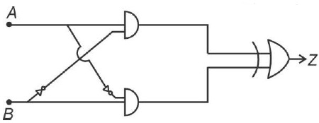
Which is correct truth table for given circuit?
Correct Answer :
| A | B | Z |
| 0 | 0 | 0 |
| 0 | 1 | 1 |
| 1 | 0 | 1 |
| 1 | 1 | 0 |
Solution :
The correct truth table for the given circuit is:
| A | B | Z |
|---|---|---|
| 0 | 0 | 0 |
| 0 | 1 | 1 |
| 1 | 0 | 1 |
| 1 | 1 | 0 |
Step-by-Step Analysis of the Logic Circuit:
1. Identify the Logic Gates and Connections:
- The circuit has two inputs labeled A and B on the left.
- There are two AND gates in the middle.
- There are two NOT gates (inverters) connected to the input branch lines.
- The final gate on the right is an OR (or XOR) gate producing output Z.
2. Determine the Output of the Top AND Gate:
- One input is taken directly from the input wire of A.
- The other input is taken from the input wire of B and passed through a NOT gate. Therefore, this input is (NOT B).
- Thus, the output of the top AND gate is:
3. Determine the Output of the Bottom AND Gate:
- One input is taken from the input wire of A and passed through a NOT gate, resulting in (NOT A).
- The other input is taken directly from the input wire of B.
- Thus, the output of the bottom AND gate is:
4. Find the Final Output Function (Z):
- The final gate combines the two outputs and .
- Assuming an OR gate at the end, the output expression is:
- This expression represents the standard logic formula for a 2-input XOR (Exclusive OR) gate:
5. Construct the Truth Table:
- Let's evaluate the output for all possible combinations of inputs:
- If and :
- If and :
- If and :
- If and :
Access expert-curated educational resources and study materials—completely free.
Create, conduct, and manage professional online assessments with Crey. Perfect for teachers and institutes.
Copyright © 2026 Crey. All Rights Reserved.