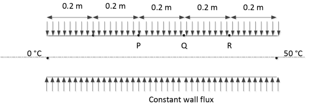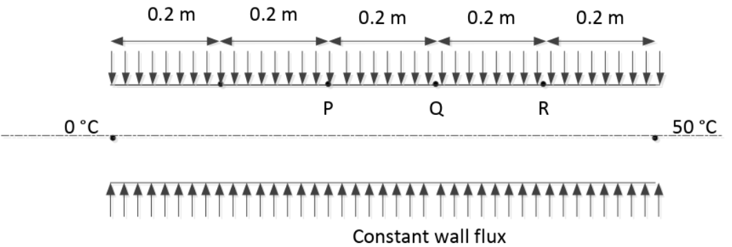
The wall of a constant diameter pipe of length 1 m is heated uniformly with flux q′′ by wrapping a heater coil around it. The flow at the inlet to the pipe is hydrodynamically fully developed. The fluid is incompressible and the flow is assumed to be laminar and steady all through the pipe. The bulk temperature of the fluid is equal to 0°C at the inlet and 50°C at the exit. The wall temperatures are measured at three locations, P, Q and R, as shown in the figure. The flow thermally develops after some distance from the inlet. The following measurements are made:
| Point | P | Q | R |
| Wall Temp(°C) | 50 | 80 | 90 |
Among the locations P, Q and R, the flow is thermally developed at
Correct Answer :
Q and R only
Solution :
The correct answer is Q and R only.
1. Physical Principles of Uniform Wall Heat Flux ():
For a steady, incompressible, laminar flow in a pipe of constant diameter heated with a constant surface heat flux , the rate of heat addition per unit length is constant.
According to the first law of thermodynamics, the local bulk (mean) temperature of the fluid at any axial location along the pipe increases linearly from the inlet:
where:
• is the bulk temperature at the inlet (),
• is the perimeter of the pipe,
• is the mass flow rate, and
• is the specific heat capacity of the fluid.
2. Identifying the Thermally Fully Developed Region:
Newton's law of cooling relates the constant heat flux to the wall temperature and bulk temperature :
where is the convection heat transfer coefficient.
In the thermally fully developed region, the heat transfer coefficient becomes constant along the length of the pipe. Because is also constant, the temperature difference between the inner wall and the bulk fluid must remain constant:
3. Verification using the Given Measurement Locations:
The total length of the pipe is .
The bulk temperatures at the inlet and exit are:
• at
• at
Using the linear distribution of the bulk temperature:
From the schematic layout, the sensors P, Q, and R are located at:
• Point P:
• Point Q:
• Point R:
Now, we calculate the bulk temperatures at each location:
•
•
•
Next, we determine the temperature difference at each location using the measured wall temperatures:
• At Point P:
• At Point Q:
• At Point R:
Since the temperature difference is identical at locations Q and R (both equaling ), the heat transfer coefficient is constant over this segment. Therefore, the flow is thermally developed at Q and R only.
Access expert-curated educational resources and study materials—completely free.
Create, conduct, and manage professional online assessments with Crey. Perfect for teachers and institutes.
Copyright © 2026 Crey. All Rights Reserved.