Question Details

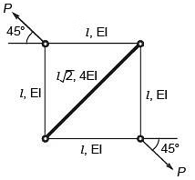
The truss shown in the figure has four members of length l and flexural rigidity EI, and one member of length l√2 and flexural rigidity 4EI. The truss is loaded by a pair of forces of magnitude P, as shown in the figure.

The smallest value of P, at which any of the truss members will buckle is

Options

A

2 π 2 E I l 2

B

π 2 E I l 2

C

2 π 2 E I l 2

D

π 2 E I 2 l 2

Correct Answer :

2 π 2 E I l 2

Solution :

The correct option/answer is:

2 η 2 E I l 2 Wait, the symbol for pi is π. Let's write the correct MathML for the option: 2 π 2 E I l 2

Step-by-Step Explanation:

1. Understanding the Truss and Applied Forces
Let us label the joints of the square truss to trace the forces clearly:

  • Bottom-left joint as A
  • Top-left joint as B
  • Top-right joint as C
  • Bottom-right joint as D
From the provided image, we have:
  • Four outer members: AB, BC, CD, and DA, each having a length of l and flexural rigidity EI.
  • One diagonal member: AC (connecting the bottom-left joint to the top-right joint) with a length of l2 and flexural rigidity 4EI.
  • Two outward external forces of magnitude P are applied at joint B (top-left) and joint D (bottom-right) along the diagonal line of action at an angle of 45° to the horizontal.

2. Analyzing Joint Equilibrium and Member Forces
Let us resolve the force P at joint B (top-left) into horizontal and vertical components:
Px = P cos ( 45 ) = P 2 (directed to the left)
Py = P sin ( 45 ) = P 2 (directed upwards)
Since joint B has only horizontal member BC and vertical member AB connected to it:

  • The horizontal force component Px must be balanced by the horizontal member BC, resulting in a tensile force of P2 in member BC.
  • The vertical force component Py must be balanced by the vertical member AB, resulting in a tensile force of P2 in member AB.
By symmetry, at joint D (bottom-right), the horizontal member CD and vertical member AD are also subjected to tensile forces of magnitude P2.

Since tensile forces stabilize members against buckling, the outer four members (AB, BC, CD, AD) will not buckle.

3. Determining the Compressive Force in the Diagonal Member AC
Let us analyze the equilibrium at joint C (top-right):

  • Member BC pulls joint C to the left with a force of P2.
  • Member CD pulls joint C downwards with a force of P2.
To balance these forces, the diagonal member AC (which is oriented at 45° to the horizontal) must push joint C to the right and upwards, indicating that the diagonal member is in compression.
Letting FAC be the compressive force in member AC, we resolve the forces horizontally:
FAC cos ( 45 ) = P 2
FAC ( 12 ) = P 2
FAC = P
Thus, the diagonal member AC experiences a compressive force equal to the applied load P.

4. Critical Buckling Load of the Diagonal Member
Since only the diagonal member AC is in compression, buckling will occur when the compressive force in AC reaches its Euler critical buckling load (Pcr).
The diagonal member is pin-connected at both ends, so the effective length is equal to its actual length:
L = l 2
The flexural rigidity of the diagonal member is:
E Idiag = 4 E I
Using Euler's buckling formula for a pin-jointed column:
Pcr = π2 ( E Idiag ) L2
Substituting the parameters of member AC:
Pcr = π2 ( 4 E I ) (l2)2
Pcr = 4 π2 E I 2 l2
Pcr = 2 π2 E I l2
Because the force in the diagonal member is exactly P, the smallest external force P at which buckling will occur in any member of the truss is:
P = 2 π2 E I l2

Unlock Our Free Library

Access expert-curated educational resources and study materials—completely free.