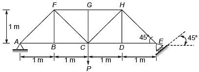
The members carrying zero force (i.e. zero-force members) in the truss shown in the figure, for any load P > 0 with no appreciable deformation of the truss (i.e. with no appreciable change in angles between the members), are
Correct Answer :
Solution :
The correct answer is BF and DH only.
Step-by-Step Explanation:
To identify the zero-force members in the given truss, we can use the method of joints and apply the standard rules for identifying zero-force members:
Rule for Three-Member Joints:
If three members meet at a joint where no external load or support reaction is applied, and two of the members are collinear (lying along the same straight line), then the third non-collinear member must carry zero force.
Let's analyze the joints of interest from the truss shown in the image:
1. Analysis at Joint B:
Joint B is located along the bottom chord, positioned 1 m from support A. The members connected to joint B are AB, BC, and BF.
- Members AB and BC are collinear along the horizontal direction.
- Member BF is a vertical member (non-collinear).
- There is no external load or support reaction acting at joint B.
By setting up the equilibrium equation in the vertical (y) direction at joint B:
Therefore, BF is a zero-force member.
2. Analysis at Joint D:
Joint D is located along the bottom chord, positioned 1 m from support E. The members connected to joint D are CD, DE, and DH.
- Members CD and DE are collinear along the horizontal direction.
- Member DH is a vertical member (non-collinear).
- There is no external load or support reaction acting at joint D.
By setting up the equilibrium equation in the vertical (y) direction at joint D:
Therefore, DH is a zero-force member.
Consequently, the members carrying zero force are BF and DH only.
Access expert-curated educational resources and study materials—completely free.
Create, conduct, and manage professional online assessments with Crey. Perfect for teachers and institutes.
Copyright © 2026 Crey. All Rights Reserved.