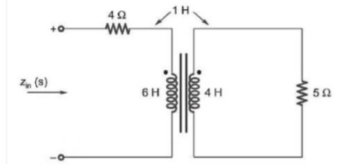
The input impedance, Zin (s), for the network shown is
Correct Answer :
Solution :
The correct answer is:
Step-by-Step Explanation:
By analyzing the circuit diagram, we identify the following components and parameters:
1. Primary Side: A resistor of value in series with a self-inductance coil of .
2. Secondary Side: A self-inductance coil of connected in a closed loop with a resistor of value .
3. Mutual Inductance: The mutual coupling between the two inductors is , indicated by the arrows pointing to the top of both coils.
4. Dot Convention: The dots are positioned at the top of both the primary and secondary inductors.
Let be the current flowing into the positive terminal of the primary loop, and let be the induced current flowing in the secondary loop (assumed clockwise, so it also enters the dotted terminal of the secondary inductor). We can write the Kirchhoff's Voltage Law (KVL) equations in the s-domain for both loops.
Loop 1 (Primary Loop):
Substituting the values , , and :
Loop 2 (Secondary Loop):
Substituting the values , , and :
Solving for in terms of :
Finding Input Impedance :
Substitute Equation 2 into Equation 1:
Factor out to find the impedance ratio :
Combine terms over a common denominator:
Expand the numerator:
Subtracting gives:
Access expert-curated educational resources and study materials—completely free.
Create, conduct, and manage professional online assessments with Crey. Perfect for teachers and institutes.
Copyright © 2026 Crey. All Rights Reserved.