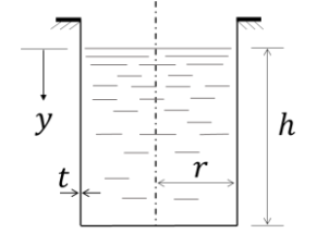
The figure shows a thin-walled open-top cylindrical vessel of radius 𝑟 and wall thickness 𝑡. The vessel is held along the brim and contains a constant-density liquid to height ℎ from the base. Neglect atmospheric pressure, the weight of the vessel and bending stresses in the vessel walls.
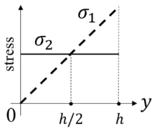
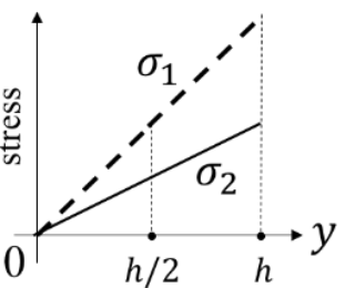
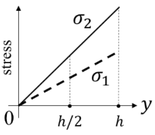
Which one of the plots depicts qualitatively CORRECT dependence of the magnitudes of axial wall stress (σ1) and circumferential wall stress (σ2) on 𝑦?
Correct Answer :
Solution :
Correct Answer:
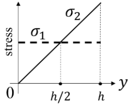
The plot showing that the axial stress () remains constant along the depth while the circumferential stress () increases linearly from zero at to its maximum at (intersecting at ) is the correct representation.
Step-by-Step Explanation:
1. Coordinate System and Hydrostatic Pressure:
As shown in the schematic diagram of the thin-walled open-top cylindrical vessel of radius and wall thickness , the coordinate starts at the free surface of the liquid and points vertically downwards towards the base.
The liquid has a constant density and is filled to a height from the base. Neglecting atmospheric pressure, the gauge hydrostatic pressure at any depth (where ) is given by:
2. Circumferential (Hoop) Wall Stress ():
For a thin-walled cylinder subjected to internal pressure , the circumferential (or hoop) stress at any depth is calculated as:
This shows that the circumferential stress varies linearly with depth :
• At the liquid surface ():
• At the bottom base ():
3. Axial Wall Stress ():
Since the vessel is held at the brim (suspended from the top), let us consider the vertical force equilibrium of the vessel section below a given plane at depth :
• The vertical cylindrical wall is straight, so the radial hydrostatic pressure on the vertical sides has no vertical component.
• The total downward force acting on this lower segment is due to the hydrostatic pressure at the base plate (), which is:
• This downward force is balanced entirely by the upward tensile force in the cylindrical wall at the section :
Equating the upward and downward forces:
Solving for the axial stress :
Since the parameters , , , , and are constants, the axial stress is uniform and constant along the entire wet length of the cylinder ().
4. Point of Intersection:
By equating the two stress equations:
Thus, the curves of and cross exactly at the midpoint . This behavior corresponds perfectly to the plot in the correct option.
Access expert-curated educational resources and study materials—completely free.
Create, conduct, and manage professional online assessments with Crey. Perfect for teachers and institutes.
Copyright © 2026 Crey. All Rights Reserved.