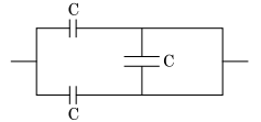
The equivalent capacitance of the combination shown in the figure is :
Correct Answer :
Solution :
The correct option is 2C.
To find the equivalent capacitance between the left and right terminals, let us label the nodes in the given circuit diagram:
1. Let the input terminal on the left side be A.
2. Let the output terminal on the right side be B.
3. Let the node just after the top-left capacitor be X.
4. Let the node just after the bottom-left capacitor be Y.
From the diagram, we can observe that both node X and node Y are directly connected to the right terminal B by simple conducting wires. Because these points are connected directly without any components between them, node X, node Y, and terminal B are all at the same electrical potential. Effectively, they form a single node.
Now, let us analyze the three capacitors in the circuit:
1. The middle vertical capacitor:
This capacitor of capacitance C is connected between node X and node Y. Since node X and node Y are at the same potential (both are connected directly to terminal B), the potential difference across this capacitor is zero:
Because the potential difference is zero, no charge is stored by this capacitor, meaning it is short-circuited and can be ignored when calculating the equivalent capacitance.
2. The top-left capacitor:
This capacitor of capacitance C is connected between terminal A and node X (which is terminal B).
3. The bottom-left capacitor:
This capacitor of capacitance C is connected between terminal A and node Y (which is terminal B).
Therefore, the top-left and bottom-left capacitors are connected in parallel across the terminals A and B.
The equivalent capacitance () for two capacitors connected in parallel is the sum of their individual capacitances:
Access expert-curated educational resources and study materials—completely free.
Create, conduct, and manage professional online assessments with Crey. Perfect for teachers and institutes.
Copyright © 2026 Crey. All Rights Reserved.