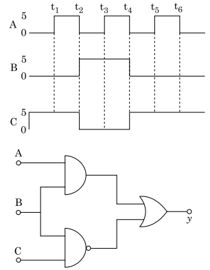
For the given circuit, the input digital signals are applied at the terminals A, B and C. What would be the output at the terminal y ?
Correct Answer :
Solution :
The correct answer is the waveform representing a constant voltage of 5 V.
Step-by-step Analysis:
1. Logic Circuit Equations:
From the given circuit diagram:
- The top gate is a two-input AND gate with inputs and . Its output is:
- The bottom gate is a two-input NAND gate with inputs and . Its output is:
- The final output gate is an OR gate that takes and as inputs. Thus, the output is:
2. Analyzing Waveforms Interval-by-Interval:
We translate the voltage levels from the input graphs (where 0 V is logic 0 and 5 V is logic 1):
• For interval :
, ,
(5 V)
• For interval :
, ,
(5 V)
• For interval :
, ,
(5 V)
• For interval :
, ,
(5 V)
• For interval :
, ,
(5 V)
• For interval :
, ,
(5 V)
• For interval :
, ,
(5 V)
Conclusion:
Since the output is logic 1 (high level, 5 V) during all intervals, the output terminal remains at a constant potential of 5 V.
Access expert-curated educational resources and study materials—completely free.
Create, conduct, and manage professional online assessments with Crey. Perfect for teachers and institutes.
Copyright © 2026 Crey. All Rights Reserved.