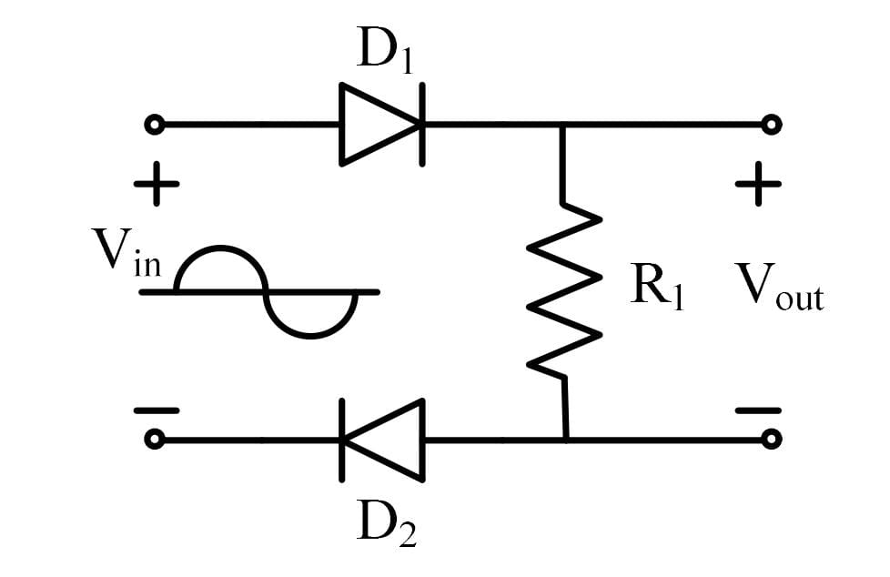
For the circuit shown below with ideal diodes, the output will be
Correct Answer :
Vout=Vin for Vin > 0
Solution :
Correct Answer:
for
Detailed Explanation:
Let us analyze the given circuit diagram under the two possible states of the input voltage, , assuming ideal diodes and as shown in the image:
Case 1: When the input voltage is positive ()
- The upper input terminal becomes positive with respect to the lower input terminal.
- The anode of diode is connected to the positive terminal of the input source, making it forward-biased (ON). Since the diode is ideal, it behaves as a short circuit (a closed switch).
- The cathode of diode is connected to the negative terminal of the input source. Current flows from the positive terminal of the input, through the closed switch of , down through the load resistor , and back through the anode of to its cathode. This makes diode forward-biased (ON) as well, behaving as a short circuit.
- With both ideal diodes conducting, the output voltage terminals are connected directly across the input voltage terminals.
- Therefore, the output voltage is given by:
Case 2: When the input voltage is negative ()
- The upper input terminal is negative with respect to the lower input terminal.
- This polarity reverse-biases both diodes (anode is negative) and (cathode is positive), turning them OFF. Under ideal conditions, they act as open circuits (open switches).
- Because the conducting path is broken, no current flows through the resistor .
- Therefore, the output voltage across the resistor is:
Comparing these derivations with the options provided, the output behavior matches:
for
Access expert-curated educational resources and study materials—completely free.
Create, conduct, and manage professional online assessments with Crey. Perfect for teachers and institutes.
Copyright © 2026 Crey. All Rights Reserved.