
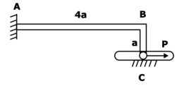
An L-shaped member ABC with slender arms AB and BC of uniform cross-section is clamped at end A and connected to a pin at end C. The pin remains in continuous contact with and is constrained to move in a smooth horizontal slot. The section modulus of the member is same in both the arms. The end C is subjected to a horizontal force 𝑃 and all the deflections are in the plane of the figure. Given the length AB is 4𝑎 and length BC is 𝑎, the magnitude and direction of the normal force on the pin from the slot, respectively, are
Correct Answer :
Solution :
Correct Answer: 3P/8, and downwards
Analysis of the Given Structure:
Based on the provided schematic diagram (Image 0 and Image 1), we have an L-shaped structural member consisting of a horizontal arm AB of length and a vertical arm BC of length . The member is fixed (clamped) at end A, and connected to a pin at end C.
The pin at C is constrained to move within a smooth horizontal slot, meaning it can translate horizontally but is prevented from translating vertically. Thus, the net vertical deflection of the pin at C must be zero:
A horizontal force is applied at end C towards the right. To maintain the vertical constraint, the slot exerts a vertical normal reaction force on the pin at C. We will determine the magnitude and direction of this normal force by applying the principle of superposition to ensure the total vertical displacement at C is zero.
Step 1: Vertical Deflection at C due to Horizontal Load P
When a horizontal force acts at C, it is transmitted through the vertical member BC to the joint B.
For the vertical member BC to remain in equilibrium:
- The force at C (acting to the right) creates a bending moment at joint B of magnitude:
This moment acts clockwise on the horizontal beam AB at end B. A clockwise moment at the free end of a cantilever beam AB causes the beam to bend upwards.
The vertical deflection at B (and consequently at C, assuming the vertical member is axially rigid) due to this end moment on a cantilever of length is:
Step 2: Vertical Deflection at C due to Normal Force F
Let be the vertical reaction force acting downwards at C to counteract the upward deflection. Since the vertical member BC is axially rigid, this vertical force is transmitted directly as a vertical point load acting downwards at the free end B of the cantilever beam AB.
The vertical deflection at B (and C) due to a downward point load at the end of the cantilever of length is:
Step 3: Compatibility Condition
For the pin to remain in the horizontal slot, the net vertical displacement must be zero:
Substituting the expressions derived in Step 1 and Step 2:
Solving for :
Since the deflection caused by the horizontal load was upwards, the resisting normal force from the slot must act in the downward direction to keep the pin in the slot.
Access expert-curated educational resources and study materials—completely free.
Create, conduct, and manage professional online assessments with Crey. Perfect for teachers and institutes.
Copyright © 2026 Crey. All Rights Reserved.